How to repair a CFL bulb?
This page will describe how to repair a faulty CFL bulb.
Dismantle the faulty CFL bulb, first. This requires a bit of patience and alertness as some bulbs are difficult to disassemble and it is hazardous if you break the glass. After separating the ballast, closely observe the circuit.
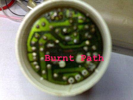
In some ballast circuits there is a fuse or a 10 Ω resistor as a fuse. First check whether it is O.K. Sometimes there may be burnt paths in the PCB, or there may be burnt, cracked or blasted components. Usually these are transistors, resistors and capacitors.
If so, you can clean the circuit board
and retrace the burnt path and repair it or else you can simply replace the
faulty item with new ones. Make sure to keep the correct pin arrangement when
you replace a component.
If there is no prominent
visible fault, then check each item with a digital multimeter. You can
do it without desoldering any component.
First check the two transistors. In many cases this is the most vulnerable item. Locate the three nodes of the both transistors on the PCB. Place the two multimeter leads on two of them and note the reading. Check the same two nodes of the other transistor and the reading should be nearly the same. If not one is faulty. Then you can check if one transistor is out of order or short circuited. If so, replace this with an equivalent transistor. According to my experience, most of the time MJE13001, or 13003 will do the job perfectly.
If a transistor is out, then,
most probably a close by resistor is out. You can check all the
resistors while they are on the board itself. They should give a very
close reading to their values according to the color code.
After that, check whether the diodes are O.K. They should conduct only in one-way. In some ballast circuits there is an item called Diac usually marked 'DB3'. This cannot be checked with a multimeter. But don't worry it is very very unlikely that the bulb doesn't light due to its fault.
If you have a digital multimeter which can check capacitors ( like Model No. DT 9205) then you can check each capacitor for faults. This of course is very seldom.
Finally, check the continuity of the two inductor coils and the PCB paths. I have experienced one CFL ballast which had all the components functioning perfectly but it failed merely due to an improper solder joint in one end of an inductor coil.
The following link was really helpful for me to understand the ballast circuit electronics in repairing the CFL bulbs.